
Distributed Acoustic Sensing: Detection Of Adversary Fires Through Battlefield Fog!

Source-microflown-avisa.com
Sound ranging (SR) systems have been the traditional bulwark for locating enemy artillery since World War I. Modern SR systems are also capable of extending such locating capability to the adversary’s small arms (SA) fire and also to the detection of Improvised Explosive Devices (IED). However, all modern conventional SR systems are linked by the common thread of use of an array of microphones (mics) with accurately surveyed locations to capture the emanated sound from such sound sources to work out the location of the sound source by computation, after duly accommodating for weather and survey/other possible errors.
SR systems suffer from certain distinct disadvantages as elucidated below: –
- Inaccuracies caused in location of sound sources due to sensitivity of SR systems to meteorological conditions- ambient temperature at both source and mics, wind speed/direction, air density etc.
- Difficulty in achieving pinpoint locations due to diffusion/dissipation of sound with increasing distance between source and mics.
- In a contested/ congested battlefield environment, such systems may also be activated by own Artillery/SA fire or may compute inaccurate locations due to ambient chaotic sound, thus undermining their reliability.
- Mics need to be accurately surveyed before deployment and physical communication channels laid- a time-consuming, tenuous and undesirable facet in fluid, rapidly shifting battlefield situations (this advantage is however, partially offset by the advent now of GPS-enabled, mobile, mounted SR systems, with inbuilt wireless communications).
Are these disadvantages enough to render SR systems operationally obsolete? Apparently not, as the following advantages of an SR system bring out (read more about the trends/ current technology in SR systems @ https://chanakyaforum.com/sound-ranging-systems-pivotal-assets-for-weapon-location/ ):-
- The passive nature of SR systems means that these systems can remain deployed in relative secrecy, while continuing to perform location tasks. This allows SR systems to work without loss of efficiency in an electronic warfare (EW) intensive environment, which would adversely affect the continued functioning of active emitters like Weapon Locating Radars (WLR). The Russia-Ukraine war, with reference to the recent continued fighting in Eastern Ukraine, have clearly demonstrated the vulnerability of WLR to kinetic ground/air action as well as electromagnetic degradation.
- SR systems can act as ‘cueing’ systems which would indicate time/direction of firing of enemy Artillery/SA for other active emitters like WLRs to be activated and oriented towards the affected sector, thus maximizing operational advantage.
- Unavoidable gaps in WLR coverage caused by lack of numbers can be effectively plugged by SR systems which can cover a large frontage and offer 360º coverage. Also, the significantly lower cost of SR systems means that a large number could be acquired for deployment to ensure gap-free coverage.
If the above are the pros and cons of an operationally deployed SR system, then it is worthwhile to examine the prospects of emerging technology that would overcome all or most of the described shortcomings, while retaining the imperative advantages that have made SR systems a vital cog in war-waging efforts around the globe since the first World War. Thus emerges the unabated interest with which land forces around the world are watching the developments in Distributed Acoustic Sensing Systems (DAS). While DAS is achieving widespread applicability in maritime operations, this article will principally focus on the developing DAS technology for the land battle.
What are DAS?
DAS is an umbrella moniker that could cover many emerging technologies for acoustic sensing. One such development refers to a technology that enables continuous, real-time measurements of acoustic signals by a deployed optical fibre cable (OFC). Unlike traditional SR systems that rely on deployed mics to pick up acoustic signals only at pre-determined points, DAS utilises the entire length of a deployed OFC to pick up these signals, thus enabling accurate computation of location of sound sources for early retaliation, as also allowing detection over large distances. In this case, the OFC thus becomes the sensing element and acoustic measurements are made and processed using an attached/ mounted optoelectronic device- a device that can detect and measure light signals/ disturbances. Such DAS have found some applicability in the maritime domain. However, these systems must also cater for internal reflections of the pulses inside the OFC, which would significantly affect accurate location computation. Also, while this technology does find tremendous utility in industrial diagnostics (eg:- checking pipeline integrity etc.), it would encounter the obvious challenge of laying/ relaying the OFC in case of damage/ fluid operations, which might preclude the use of this cutting-edge technology in battlefield environments. This technology is not discussed further.
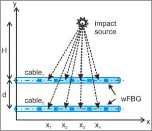
Schematic Diagram of an OFC Based DAS: Source – mdpi.com
{H-Distance from OFC to Sound Source; d-Distance between two OFC Arrays; x1,x2…- Location of weak Fibre Bragg Gratings (wFBG)- low cost optical filters built into the OFC to block certain wavelengths}
A variant of DAS technology uses Acoustic Vector Sensor (AVS) Arrays to create an accurate acoustic map of the tactical battle area. Mic arrays in conventional SR systems only sense changes in atmospheric pressure caused by propagation of sound waves produced due to firing of the adversary’s weapon systems (hereinafter referred to as the sound source). The time differential in receipt of these pressure changes (i.e. sound) by the mic array allows a conventional SR system to work out the location of the sound source. However, it must be remembered that these pressure differentials are scalar quantities that in standalone capacity, do not indicate the direction of the sound source. The use of such a method for detection of a sound source would naturally result in tenuous, low-accuracy location, plagued by inaccuracies due to simultaneous receipt of aural inputs from other battlefield noises. In contrast, AVS arrays measure the velocity of the propagated acoustic wave (a vector quantity with direction), as well changes in pressure, as explained above. By exploiting this extra information, AVS arrays can significantly improve accuracy of detection of sound source location.
How Does AVS Work?
AVS typically works by detecting and measuring the temperature difference between low(er)/high(er) frequency (HF/LF) sounds propagated from sound sources during the process of firing. Since the HF sounds would result in a higher velocity of particles of the medium (air) and the LF sounds would cause a lower particle velocity, the passage of the HF/LF sounds over two metallic strips (wires) would result in a difference in resistance (causing difference in temperature) in the wires, which could be measured electrically to determine the velocity of the propagated sound wave. Practically, the wires are heated to a temperature much higher (about 200ºC greater) than the ambient temperature. As air flows across the AVS, the upstream wire (relative to direction of propagation of the pressure wave) marginally cools down by giving off some heat to the passing cool air. The downstream wire encounters this previously heated air and thus only cools down to a lesser extent. The difference in temperature between the two wires is measured electrically, and since the location of the wires, distance between them and the time interval of cooling of the wires is known, this makes it possible to measure the velocity of the propagated particles directly, which gives the direction from which the wave has been propagated.

AVS (With Size Comparison) Showing Parallel Metallic Wires Integrated Onto One Single Chip For Determining Velocity of Propagated Sound Wave: Source – Microflown Technologies
Advantages of AVS Arrays. The following advantages accrue over standard SR systems using deployed mic arrays:-
- Increased acoustic bandwidth to detect sound sources with various frequencies/ wavelengths (referring to fires from different types of weapon systems being used by the adversary in the tactical battlefield). Far-field, all-weather detection of sound sources means that AVS arrays can be deployed far further within friendly territory, even in inclement weather, thus minimising the requirement of redeployment and reducing the danger of degradation due to enemy fires/action.
- Since each deployed AVS can detect velocity and therefore direction of incoming sound waves, the shortcoming of inaccurate location detection due to ambient noise caused due to simultaneous propagation of own and adversary sound sources is obviated, since the AVS can be cued via algorithms to only detect sound sources within a particular directional arc. This directional capability thus significantly reduces the signal-to-noise ratio, aiding in more accurate location computation of the sound source.
- Ability to identify multiple sources with a single AVS, thus contributing to reduced system size and consequent lower logistics burden in transportation/ setting up.
- Higher accuracy of sound source location with a smaller AVS array size, thus reducing set-up times when compared to standard SR systems.
- Uses endfire array configuration (where the AVS are deployed along/parallel to the anticipated direction of the adversary’s sound sources) to maximise accuracy of location of the sound source.
- AVS lends itself to dispersed or distributed deployment without any fixed configuration, thus enhancing flexibility on the battlefield.
AVS Application
Some significant developments in battlefield AVS technology include development of AVS capable of achieving 3D directionality (location in the x, y and z axes) in the acoustic domain. A Dutch Firm, Microflown AVISA, has pioneered a hardwired acoustic subarray of four such Acoustic Multi Mission Sensors ( AMMS), which the Firm has dubbed the ‘CASTLE’ configuration. The AMMS are created by combining two orthogonally (right-angled) placed transducers (devices to convert variations in soundwave pressure into electric signals) and a microphone into a single wind/weather proof unit. Each AMMS in itself provides directional information of the propagated sound wave from the sound source. This configuration is capable of operating over large frequency ranges (~10Hz to 10kHz- this covers almost all battlefield sounds) with AI-enabled self-learning for processing of acoustic signals to achieve 3D directionality of the sound source. Such AVS arrays could be used for detection of a multitude of sound sources- from Unmanned Aerial Vehicles, to SA/ Artillery fire.

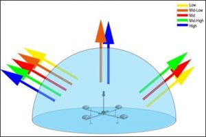
CASTLE AVS Array Showing 4 AMMS, an Acoustic Master (for Signal Processing ) and a Weather Station (for Meteorological Data); Multi-Frequency/ Multi-Directional Detection ‘Bubble’ Created by CASTLE: Source-linkedin.com
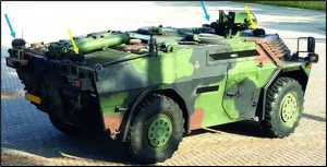
Mobile Sound Ranging Array (MSRA) Mounted on a High Mobility Vehicle: Source – microflown-avisa.com

An AVS Capable of Measuring Sound Wave Pressure and Particle Velocity-the Actual ½” Probe(L), Cross-Section of the Probe (C) and Size Comparison with a Matchhead(R): Source – semanticscholar.org
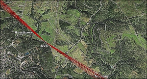
Map Showing Detection of Artillery Howitzer and Mortar Fires with a Single Deployed AVS: Source – semanticscholar.org
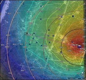
An Acoustic ‘Heatmap’ Indicating Areas of Different Sound Source Intensity achieved through Collaborative DAS on the Battlefield: Source – Microflown AVISA via linkedin.com
US DARPA’s Distributed Agile Submarine Hunting (DASH) Program. The DASH program showcases maritime application of DAS and envisages advanced stand-off sensing of submarines by deep-ocean unmanned distributed acoustic sensors. The technology (hitherto fore beyond reach due to the requirement of big-data processing to be able to infer a submarine’s bearing, distance and velocity from the received disturbances) employs submerged distributed deep-ocean sonar nodes. A collaborative network of such distributed sensor nodes would permit detection of adversary submarines over a large ocean space. One of the prototypes developed for the DASH program is the Transformational Reliable Acoustic Path System (TRAPS). TRAPS is an expendable, rapidly deployable, low-power/cost, fixed passive acoustic node designed to achieve large-area coverage by exploiting advantages of operating from large depths underwater. These nodes would communicate with a surface node via acoustic modems for further transmission to linked satellites to disburse information on detection/location of adversary submarines.
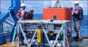
TRAPS Being Deployed: Source – navalnews.com
Conclusion
The advent of low-cost deployable Distributed Acoustic Sensors in the tactical/maritime battlefield represents a paradigm shift towards advancements in passive detection and location technology. The ability of such systems to function in a contested environment either in standalone or collaborative mode would accord unprecedented operational flexibility to the Commander in the field with respect to real-time detection and location of enemy fires, even in cluttered aural and EW environments.
Disclaimer
The opinions expressed in this article are the author’s own and do not reflect the views of Chanakya Forum. All information provided in this article including timeliness, completeness, accuracy, suitability or validity of information referenced therein, is the sole responsibility of the author. www.chanakyaforum.com does not assume any responsibility for the same.
Chanakya Forum is now on . Click here to join our channel (@ChanakyaForum) and stay updated with the latest headlines and articles.
Important
We work round the clock to bring you the finest articles and updates from around the world. There is a team that works tirelessly to ensure that you have a seamless reading experience. But all this costs money. Please support us so that we keep doing what we do best. Happy Reading
Support Us











POST COMMENTS (0)